This is a tutorial for the first steps of modeling a graph in jABC4. Every graph is a representation of a (business) process that describes what happens by using activities for every step. The workflow of this basic tutorial uses the example of modeling a Chainreaction game strategy, as described on the Introduction to Chainreaction page.
In this tutorial you will
Creating new graphs from scratch and further tasks are presented in the Advanced Modeling Tutorial.
A New Game Strategy
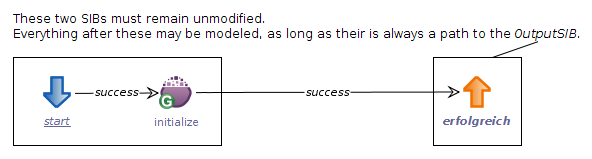
A newly generated, empty game strategy graph.
In order to create a new game strategy simply select File → New… → New Graph from Template in the menu bar. In the template selection popup, select the GameStrategyTemplate.xml and choose where the new game strategy model is saved.
A new graph model will open in the model canvas, already containing the most important basic elements: the input and output activity as well as the initialize activity which initializes the cell value with 0. At this point, the newly created model is already a valid game strategy that assigns every cell with the value 0, since the initial value is never changed.
Adding Activities
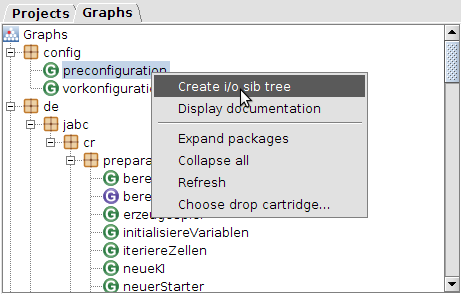
The Graphs tab on the browser area, while creating a new i/o sib tree.
Our next step is to add some deciding to the game strategy, so that basic distinctions between different situations can be made. At first we will use the activity isCornerCell to add a bonus to a cell if it is a corner cell.
The Chainreaction project comes with prepared activities including e.g. the isCornerCell activity that we will add. To access these activities, you need to switch to the graphs tab in your browser area. In the package “config” you will find a graph model named preconfiguration. Right click it and select Create i/o sib tree. This will allow you to access the preconfigured activities via a new tab in your browser area.
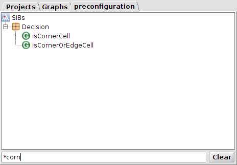
An i/o sib tree with applied filter for any graph that contains corn in its name.
Change to the preconfiguration tab. The preconfiguration tree holds prepared activities specific for Chainreaction (CR) as well as basic utility activities that are all arranged into four packages:
- Action – contains CR activities that are simply executed and don’t return results, like giving boni and mali to the cell value.
- Calculation – includes CR activities that are used to determine specific values, such as counting atoms and cells, or what the board would look like if an atom was placed in this cell.
- Decision – holds CR activities that can modify the process flow by their different branches that represent different conditions, for example isCriticalCell or isCornerCell
- Math – bundles activities for basic arithmetic such as addition etc. and comparison of two Integers.
Since we wish to give a bonus to a cell if it is a corner cell, we first need to add the associated activity to the graph model. As mentioned, the isCornerCell activity does exactly that. Either scroll down until you find the activity in the Decision package, or type it into the filter textfield at the bottom of the browser area. Now we can simply drag and drop the isCornerCell activity onto the graph canvas.
To add a bonus to the cell value, we need an addBonus activity. There are multiple activities with pre-set bonus values, for now we will take the add10Bonus activity and add it the same way.
Defining the Process Flow
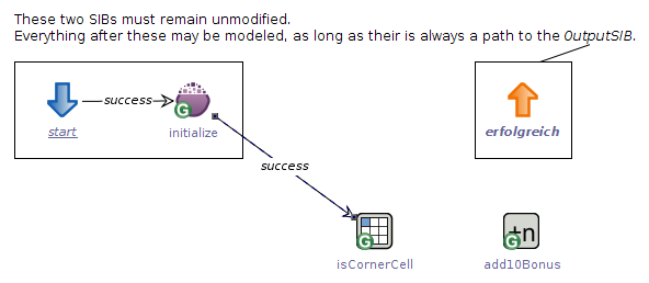
This is how the game strategy graph looks like: the added activities and the modified success branch.
Now that we have added the activities we need, the next step is to alter the process flow that is defined by the edges (“branches”) that connect the graph model activities. When a graph model is executed, the input SIB start defines the entrance point, the success branch leads to the next activity to be executed and based on the activity’s result, one of its branches is taken to the next step. Some activities such as initialize only have one branch, which is taken after the activity has been executed. Other activities such as our newly added isCornerCell introduce multiple possible branches, but more on that in a bit.
First, we need to make sure that the process flow can reach the isCornerCell activity. That means: instead of leading to the output SIB erfolgreich, the initialize activity’s success branch should point to isCornerCell so that it will be executed after the initialization. When you click a branch, its starting- and endpoint will be highlighted with little squares that serve as drag-and-drop markers. Drag the end marker of the initialize activity’s success branch and drop it onto isCornerCell.
Now the successor of initialize is the activity isCornerCell.
In this state, the graph model is no longer executable, because the activity isCornerCell has no successor and therefore the execution would terminate with an error.
What we now want to do is to add a bonus of 10 to the cell value (by use of the add10Bonus activity) if the cell is a corner cell, and do nothing if it is not. So the next step is to add a branch from isCornerCell that leads to add10Bonus and as well as another that leads directly from isCornerCell to the output SIB. We also will add a branch from add10Bonus to the output SIB, since otherwise the add10Bonus activity would have no successor (which would lead to the same problem).
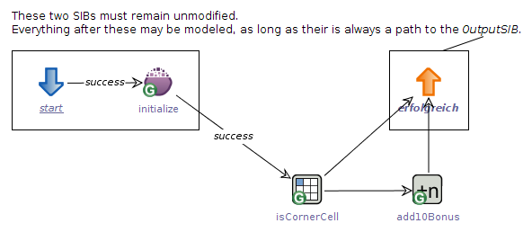
The game strategy graph with all required but not yet labeled edges.
To add a new edge from one activity to another, hold down the ⇧Shift key and drag the edge from the first activity to the desired successor. In this case, from isCornerCell to add10Bonus. After that, add an edge from add10Bonus to erfolgreich and a third one from isCornerCell to erfolgreich so that every activity eventually leads to the output SIB.
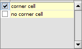
The popup for choosing branches when double-clicking an edge.
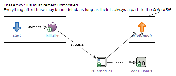
The game strategy graph with a labeled corner cell edge.
Now that we defined the successors of every activity, we need to specify in which case that successor is taken. This can be done automatically for activities with only one possible branch (e.g. add10Bonus with only the success branch) but must be set manually for activities that can have one out of multiple cases, such as isCornerCell (since a cell either is a corner cell or it is not).
When you double-click on an edge, you will see that there is a list consisting of all possible branches. These represent the cases in which an activity can be after its execution: for the add10Bonus activity this means after its successful execution, while the isCornerCell activity can be in either corner cell or no corner cell. Now, double-click on the edge that proceeds from the isCornerCell activity to add10Bonus. We wish to take that route (ergo: give a cell a bonus of 10) in case that is is a corner cell. Therefore, select the corner cell branch. The edge is now labeled with the branch we chose, to indicate that it will be taken in exactly that case.
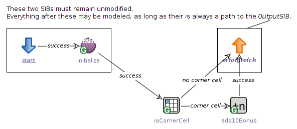
The complete game strategy graph with all labeled edges.
Finally, we could label the remaining two edges manually, since every edge needs to be labeled in order to be a valid transition between two activities. But in our case, we can let the jABC assign the unassigned edges automatically because the add10Bonus activity has only one possible branch left for its unassigned edge (its success branch) and the isCornerCell activity also has only its second branch no corner cell left unassigned.
To automatically assign all unambiguous branches, right click on the graph canvas and choose Autodefine branches. This now defines the remaining two branches according to the remaining choices, while it would leave any ambiguous branches blank.
Once every edge is labeled, our first game strategy that prefers corner cells and awards them a bonus of 10 is finished. For a short description of how to test modeled game strategies, follow this guide.
For more complex graph modeling possibilities, read more on the Advanced Modeling Tutorial.